Ferrari Life Forum banner

3.4L project

1 reading
65K views 338 replies 29 participants last post by  duck.co.za  
#1 ·
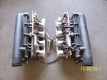
Hi everyone. Thought I would make it known what I am up to here and throw some pics up.

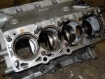
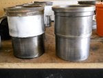
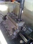
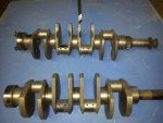
The idea is to install a 360 crank (79mm stroke) into a 2v 308 block. A little modification is required, but to my knowledge it's not a ton as the crank spins freely in the 308 block on its own. The liners were bored and honed with torque plates to 83mm. Final capacity is just a bit over 3.4L.


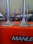
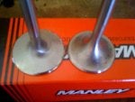
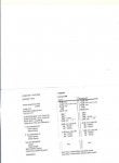
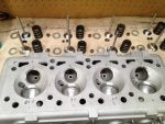
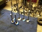
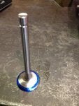
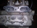
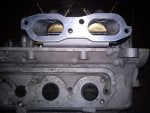
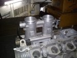
Upgraded cams from Cat Cams in Belgium with 10.75mm lift and around 248 dur @ .050. I went with advice from Steve Dermijian and opened the intake valve size to 44mm as this is what he did for Nick's engine. I also used more of a nail head style valve which also reportedly helps things quite a bit. Lastly, the intake valve seats were replaced with larger OD and ID seats and the bowls were blended to accomodate the step in the ID the new valve seat creates. Flow is reportedly 12% better yet I am still awaiting the flow sheet to confirm this. I guess most of the gain is made over .150 lift with great flow present at .350-.400 lift.


The new cams use a radical slope and we collectively believed the stock valve seat pressure was not up to the task of handling this. The stock springs use around 60lbs seat pressure with 200lbs at only .350 lift (new cams are (.425 which would put stock springs at about 230lbs which is too high IMO)) from the seat, meaning these springs have a very high spring rate. I am going with a spring which uses a bit less rate yet is a longer spring so I can have a bit more seat pressure yet about the same nose pressure. Seat pressure is set to be approx 85lbs with 220lbs at the nose, and the springs of course have plenty of room before coil bind opposed to the stock springs which would really be pushed about to capacity if I used them with this cam. These new springs are also a good 20g lighter each.

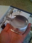
Pistons are done from JE (10.5:1 with gapless top rings)
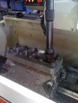
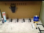
all machine work is completed (heads, block, line bore, flywheel surface, rods resized)
new clutch
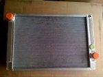
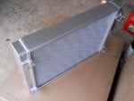
new aluminum radiator
new high torque starter
ARP rod bolts


I will probably go to injection later, but for now I will stick with carbs and run ignition timing from a 36-1 trigger wheel and a simple CPU (MJ unit) until I swap to injection.


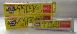
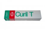
Case halves are going to be sealed up using the Porsche 911 crowd sealer of choice, namely 3bond 1194, and then Elring's Curil T for pretty much everything else.


Anyway, just waiting for the crank to show up on the boat from South Africa. The machine work can then get cracked out by our very own maistro of the lathe and Bridgeport, Mark, then of course I can throw this thing together.
 

Attachments

#2 ·
Pic of the radiator I designed and had put together. It's a crossflow design which I like far more than the stock downflow design. I didn't want to compromise the look under the front hood too much so this pretty much drops right in which the exception of having to cut about .5" from the rear portion of the radiator mounting saddle to accomodate for the extra wide radiator core. Fits perfectly otherwise and looks fantastic. About 41% more cooling fin area yet the tanks on either end do no hold quite as much fluid as the stock top and bottom radiator tanks, thus meaning this radiator -which weighs 14lbs- will actually stay lighter than the stock radiator as it's not carrying quite as much fluid.
 

Attachments

#3 ·
Cool project! Who made the radiator for you?
 
#4 ·
I have a fabricator in North Carolina who works with me on them. He does not have a shop where he does this for anyone as he is a private racecar fabricator etc. He is a great welder and made exactly what I needed per the schematic I whipped up, and he has a big 'ol pressure tank he can adequately test them in too. A few other club members actually wanted one a month or so ago so I had a few more made and sent. Actual custom aluminum radiator shops are outrageous regarding pricing for these things regardless of if I draw up the schematic etc.
 
#5 ·
That looks like a fantastic project. A 308 with a lot more reliable power is a wonderful goal.

Nice radiator. They are expensive from the custom fabricators.
 
#6 ·
I was seriously considering throwing in the towel on a 308 and getting a 355 or 360, but for me they just don't 'do it' like an old GTB. The GTBs just need a good 100bhp more though. I would be very pleased if this reaches 320-330bhp. I believe the parts are there to make this possible now.
 
#7 ·
Got the 1-4 head together last night. I *hate* installing valve stem seals on the guides. Even with the correct tool it is difficult as these guides just plain don't have anything that fits them perfectly. Anyway, it's together and it looks good.

Every last one of the new exhaust valves from Si were out of round with one being worse than the rest! The intake valves from Manley were all great except for 1 which was just a hair out. Leak checked 100% sealed. Good stuff.
 

Attachments

#8 ·
Oh, and I did a light lap with fine compound to mate the new valves to the freshly cut seats. There seems to be some controversy on whether or not to do a light lap after everything is freshly cut, but I like doing a 3 second fine lap after and they seal really well so I don't see any issue with it.
 
#14 · (Edited)
It looks great.

How do you check that the valves are out of round? Do you put them in a lathe and run the dial micrometer against the perimeter of the head?
I checked the concentricity for the valves and seats at my local machine shop yesterday. The seats are checked with a simple dial gauge tool which inserts firmly to the valve guide and is then zero'd out and turned in the seat.

I checked the valves in an old collet style kwik-way after coating the facing with dykem. The kwik-way slowly spins the valve and there is a fine grinding stone positioned 45 degrees out. Slowly bring the valve to the stone and if the stone touches part of the valve face but not the other then it is out of round. One of them was really bad yet all the exhausts were out a little. I have now learned to always check any valve like this if it is not pulling good vacuum on the new seat, new valve, old valve, whatever.
 
#11 ·
I so really like what I see going on here: NICE. Will subscribe to this thread too. Love this sort of stuff.

Keep the pics posting

rik
 
#13 ·
Nice job and my hot rod 67 Corvette had Manley valves. We always lapped the valves/seats for the best seal.
 
#17 ·
Their off-the-shelf silver line for Ferrari valves is the silver line I believe. Their quality of valves is just fine, it's just they were in a hurry to put a face on them which is why none of the faces were but 90-95% correct rather than 100% correct. I will still use them in the future as I am told this sort of thing is not uncommon with every valve manufacturer out there.
 
#19 ·
What specifically needs to be done to the 360 crank for it to work properly. Also, can you give an idea as to what kind of cost you're into so far?

Very cool project and I know many of us are looking forward to your test drive posts once you have everything back together.
 
#20 · (Edited)
I believe Mark or Dave can answer this question a little better than me, but what I do know is the damper mounting area on the 360 crank is a bit longer and that last journal on the same end is a bit shorter meaning the timing gear ring is not exactly lined up with the 308 timing gears to the tune of 5mm. A 5mm ring needs to be fabricated and placed between the last journal and the timing gear to line the two up. Also, the flywheel mounting area is .050 shorter on the 360 crank meaning either a custom flywheel needs to made or not. It could be that there is enough room created by the stock 308 flywheel that this is not an issue but I will have to find out. I will of course report once I know for sure. A 360 crank does spin freely and is about 10lbs lighter than a stock 308 crank which is definitely not a bad thing

Cost wise, I don't have an exact figure yet but I have an excel spreadsheet tracking all machining costs, parts costs, misc costs and it is over $10k now. Mind you I have done almost all of this myself so that certainly negates any labor rate. I believe Carobu who does this sort of thing gets up in the neighborhood of $25-$30k all in. Their last 3.5L QV engine with electronic injection made 347bhp. Quite a screamer. Replace with throttle bodies and they could see close to 400bhp.
 
#24 · (Edited)
Question for any physics people in the audience as my Newtonian physics as not quite what I would like it to be!

What effect will increased piston speed have on intake port velocity? By changing the stroke of this engine +8mm I am raising the piston speed yet increasing the rod angle placing a bit more load on the piston, which I am ok with. Too much port velocity can be a bad thing while too little (which I am sort of fearful of with these 44mm intakes yet 40dcnf Webers) can cause issues as well. I am thinking the stroke increase will level out what port velocity I have lost in opening the ports, but I can't be sure.


I should explain my asking a little bit. I had my 5-8 head intakes measured for flow today and I think the numbers reported to me came out ok. .050-.100 lift is reported to have just a 3% gain yet it moves up quickly to 8-9% gains at anything over .200" with .400 lift yielding a 14% gain or 167cfm. In a stock intake, .400 lift yields 147cfm so this is a good gain to me. The absolute best thing for this intake were the nailhead style valves with back cuts I am told. I didn't really have huge cash to invest in porting these things how I wanted so all I did was change the seats to a larger ID and OD, larger nailhead intake valves, and then blend the bowl into the new seat ID and blend to the throat. It was actually really easy if you take your time and make for darn sure not to cut anything too deep. The only problem is I know I lost some velocity by going to a larger seat ID and valve pinch point OD. Anyway, estimated BHP per cylinder came out at 42.8 which is 342.4bhp in this motor which is right where I want to be. Nick's heads came out to 44.9 so as long as I am within 10% of those heads I am happy. The problem is now that I know the heads can do the job I know the puny Webers are going to be struggling........ I just can't cough up the $$$$ to do the injection stuff just yet.....I will though! Give me time and I will get it on eventually. I just want to get the thing up and running again for now.
 
#29 ·
What effect will increased piston speed have on intake port velocity?.
A little but not much. The much bigger effect is the increased displacement.

The higher flow will help more than the reduced velocity hurts, so that's is a gain.

Those numbers are at 28" water? Stock head are right around 92 at 10" on the 2 flow benches I've tested on which is about 158 at 28" so the 147 number confuses me a bit..,..but they are a gain either way so that's good. 40mm webers should be good to about the 167 you have so that might be ok.
 
#25 ·
Well there just seems to be a spare set of 355 TB's laying around ! as of about 20minutes ago ??
John just bid and won a full set including injectors, fuel rails, plenums and the lot . Which is for my project and I already have a set of just the TB's here in South Africa. I'll have a look in the morning as to how hard it would be to fit them to the carb manifolds ?
Problem is you still need an ECU ? which is where the money is ? Although how is Mark coming on with his ? Would be a great test bed ?
 
#26 ·
Dave you are sneaky. Yes, the ECU is a pricey part of this, but certainly not the only part. I was sort of eyeballing the manifolds and wondering the same thing. Matching the ports and getting the 355 manifolds to mount vertically would be the tricky bit. I suppose a small manifold runner could be fabricated from the inlet port to provide the required 45 degree turn so the 355 TB's could fit upright. Not easy, but very cool.
 

Attachments

#36 ·
From Mark's thread, it seems like the goal is to get a smooth taper from the TB to the valve... looks like a tough job as is. Maybe a cross flow manifold and mount the TBs horizontally over the valve covers? Another thought is to just make a 2" or so spacer and taper from the TB down to the port. Hood clearance might be an issue though.
 
#41 ·
The length is about rpm mostly.

frequency = harmonic number x (speed of sound in the pipe)/(2)(length of the vibrating air column)

For an engine the frequency to use is f=rpm/2/60

The signal is strongest wiht the 1st harmonic and gets small as you go 2nd, 3rd, ect. Normally the 1st harmonic yields a pipe that is way to long to package under the hood (headers are normally the 1st harmonic) and on a 308 something around 19" would be the 2nd harmonic....which is also pretty long. Intakes are normally the 3rd harmonic which would be about 12.5" if 19" is the 2nd.
 
#43 ·
I think the only decent option is to saw off the head side of the manifold an inch or so below the throttle plate where the runner is still pretty round and then weld on what you need to mate to the head.

Hyabusa or similar TBs are a fine answer too but you still need to fab an intake for them so they are probably about the same amount of work to use, just cheaper to buy.